From Sample to Strategy
The process kicked off with the arrival of a used Coanda blade at our facility. A thorough visual inspection followed—wear zones, curvature, and functional geometry were logged. Early-stage documentation helped define what to scan, what to measure, and ultimately, what mattered most to replicate.
Finding the Right Alloy: LIBS to the Rescue
Before we could replicate the part, we needed to understand its material composition. Using a portable LIBS (Laser-Induced Breakdown Spectroscopy) analyzer, we identified the alloy composition on-site. This chemical fingerprint later guided our alloy melting and validation process—keeping everything in sync with the original performance specs.
Precision Capture: 3D Scanning and CAD Modeling
Using a high-resolution SHINING3D FreeScan Trak Nova 3D scanner, we digitized the part with microns accuracy. The scan data was processed in reverse engineering software to create a clean, parametric CAD model—ensuring design intent and manufacturability. This wasn’t just surface recreation; it was digital resurrection.
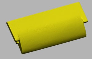
Fig 1: 3D scanning of the central blade
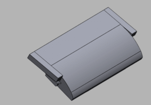
Fig 2: RE file developed from scanned data
Getting the Numbers Right: Scan-to-CAD QC
To validate the model, we used Polyworks for dimensional inspection. The scan-to-CAD comparison verified the fidelity of our digital clone against the real-world part. Deviations were analyzed, corrected, and re-checked to lock in accuracy before proceeding to production.
Design for Casting: From Drawing Board to Die Shop
With the CAD model approved, we generated 2D engineering drawings in CAD software, covering every critical dimension and tolerance. Simultaneously, we designed the casting die, incorporating shrinkage allowances, optimized gating, and risers—ensuring both flow efficiency and dimensional consistency.
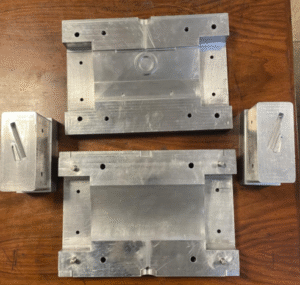
Fig 3: Die designed to produce wax pattern
Manufacturing the Die: Precision in Metal
CNC toolpaths were programmed in CAM software and executed on our in-house milling machines. The die blocks were cut with tight tolerances and polished to ensure smooth wax pattern release—because casting accuracy starts long before metal gets poured.
Wax Trees and Alloy Melts
Wax patterns were produced using the newly machined die, then assembled into trees with precision spacing for shell building. Meanwhile, we melted and verified the alloy in-house—confirming chemical composition again via LIBS to ensure material integrity before pouring.
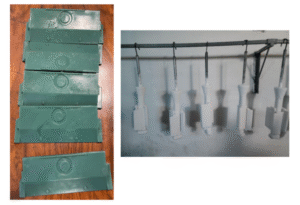
Fig 3: Die designed to produce wax pattern
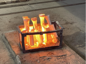
Fig 5: Metal pouring after baking shell
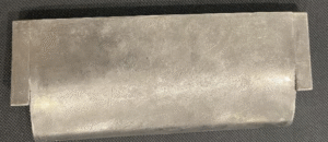
Fig 6: Final casted part
Casting it Right: ISO 9001-Certified Confidence
Shell building, burnout, and molten metal pouring were performed under strict ISO 9001 protocols. Repeatability was the goal—and we achieved it. The cast parts showed excellent fill, minimal defects, and dimensional consistency across the batch.
Post-Processing: Making the Metal Shine
After casting, each part underwent de-gating, sandblasting, and surface grinding. These finishing touches brought the components within cosmetic and functional tolerances—ensuring that what looked good also performed as needed.
Final Checks: Metrology Meets Manufacturing
Each part was 3D scanned and checked again in Polyworks. The scan-to-CAD comparisons were run against both the digital model and engineering drawings, ensuring every spec was met before sign-off. Final reports were generated, approved, and logged for QA records.
Delivery: Precision Sealed and Shipped
Before shipment, every component was cleaned, inspected one last time, and securely packaged. No shortcuts—just reliable parts delivered to the client on time, and to spec.
Key Takeaways from the Field
– Visual Analysis First: Understand the part before scanning it.
– Chemical Composition Tester: LIBS testing guides reliable casting.
– Accuracy is the Key: Scan, model, inspect—repeat until perfect.
– Design as per manufacturing process: Build manufacturing logic into your CAD.
– Quality Lives in the Details: Every tolerance matters—from die to delivery.
When reverse engineering is done right, it’s more than replication—it’s controlled reproduction with engineered precision. This Coanda wing was proof that with the right team, tools, and process, old parts can fly again.
Do you want to discuss your challenge?
Reach out to our technical team at: [email protected] | www.otspk.com


